Controller Area Network (CAN) is a robust vehicle bus standard designed to allow microcontrollers and devices to communicate with each other within a vehicle without a host computer. Developed by Bosch in the 1980s, it has become the de facto standard for in-vehicle communication in automotive systems and is also widely used in industrial automation, medical equipment, and aerospace applications.
1. What is CAN?
CAN is a multi-master, message-based protocol that enables communication between multiple electronic control units (ECUs) or nodes in a network. It is designed for high reliability, real-time performance, and fault tolerance in noisy environments.
2. Key Features of CAN
- Multi-master protocol: Any node can transmit data if the bus is free.
- Message-based communication: No node addresses; instead, messages are identified by an ID.
- Priority-based arbitration: Lower ID has higher priority.
- Error detection and fault confinement: Built-in mechanisms for robustness.
- Speeds up to 1 Mbps (Classical CAN); up to 5 Mbps (CAN FD).
3. CAN Network Architecture
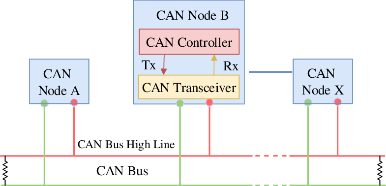
A typical CAN network consists of:
- CAN Controller: Integrated in MCU or as an external IC, handles protocol logic.
- CAN Transceiver: Converts digital signals to differential voltage signals and vice versa.
- CAN Bus (Twisted Pair): Two wires – CAN_H (High) and CAN_L (Low), used to transmit differential signals.
- CAN bus must be terminated with two 120Ω resistors at both ends
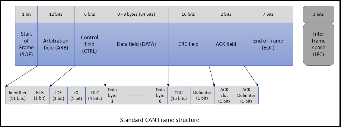
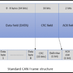
4. CAN Message Frame Structure
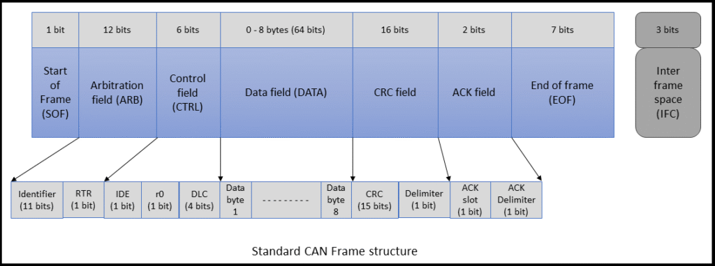
A CAN data frame has the following structure (Classical CAN):
| Field | Bits | Description |
|---|---|---|
| Start of Frame | 1 | Indicates start of message |
| Identifier | 11/29 | Message ID (standard or extended) |
| RTR Bit | 1 | Remote Transmission Request |
| IDE Bit | 1 | Identifier Extension (0 = 11-bit, 1 = 29-bit) |
| DLC (Data Length) | 4 | Number of data bytes (0–8 for classical CAN) |
| Data Field | 0–64 | Actual data bytes |
| CRC Field | 15+1 | Error checking |
| ACK Slot | 2 | Acknowledgment from receiver |
| End of Frame | 7 | End marker |
Note: CAN FD (Flexible Data Rate) supports up to 64 bytes in the data field.
5. Arbitration and Priority
When multiple nodes attempt to transmit simultaneously, bit-wise arbitration ensures that the highest-priority message (lowest ID value) wins without data loss. All nodes monitor the bus, and if a node detects a dominant bit while sending a recessive bit, it stops transmitting.
- Dominant Bit (0) overrides Recessive Bit (1) on the bus.
- Priority is determined by the identifier; lower IDs have higher priority.
6. Error Detection Mechanisms
CAN includes five types of error checks:
- Bit Error – Bit differs from what was sent.
- Stuff Error – More than five consecutive bits of the same polarity.
- CRC Error – Mismatch in CRC value.
- Form Error – Fixed-format fields are violated.
- ACK Error – No acknowledgment received.
Nodes that frequently cause errors are placed into error passive or bus-off states to protect the system.
7. Types of CAN Frames
- Data Frame – Carries data from sender to receiver.
- Remote Frame – Requests data from another node.
- Error Frame – Indicates an error has occurred.
- Overload Frame – Introduces delay between data frames.
8. Practical Use in Automotive
Modern cars can have dozens of ECUs communicating over CAN networks, such as:
- Powertrain CAN – Engine, transmission, etc.
- Body CAN – Doors, lighting, HVAC, etc.
- Infotainment CAN – Audio, navigation systems.
- Diagnostics CAN (OBD-II) – Standardized diagnostic interface.
Each subsystem may be isolated on separate CAN buses for efficiency and safety.
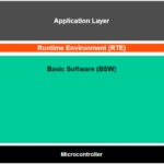
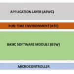
9. CAN in AUTOSAR
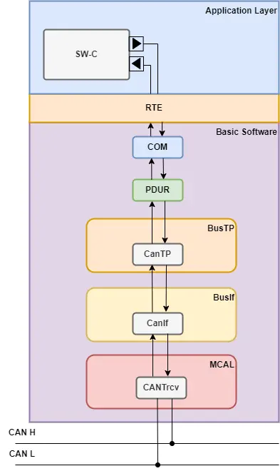
In AUTOSAR (AUTomotive Open System ARchitecture), CAN is handled through the following Basic Software (BSW) layers:
- CAN Driver – Interface to the hardware.
- CAN Interface (CanIf) – Hardware abstraction.
- PDU Router (PduR) – Routes Protocol Data Units.
- Communication Stack (COM) – Handles signal-level processing.
- Application Layer / Software Component – Uses RTE to send/receive data.

Leave a Reply