The modern automotive industry is undergoing a rapid transformation. From advanced driver-assistance systems (ADAS) to electric vehicle (EV) powertrain control, today’s vehicles rely on sophisticated software to manage safety, performance, and comfort. At the core of this software evolution lies the Real-Time Operating System (RTOS) — a lightweight yet powerful operating system tailored for time-critical embedded applications.
- How RTOS Works?
Unlike general-purpose operating systems, an RTOS is designed to ensure deterministic behavior — meaning that tasks are executed within a predictable time frame. This is critical in automotive applications, where delays or missed deadlines can directly affect safety.
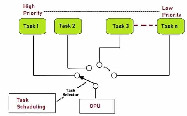
An RTOS manages system resources (CPU, memory, peripherals) by scheduling multiple tasks. Each task represents a small, independent unit of work — for example:
Task 1: Read sensor data (e.g., vehicle speed or steering angle).
Task 2: Process control algorithms (e.g., engine torque calculation).
Task 3: Update actuator signals (e.g., throttle control, braking system).
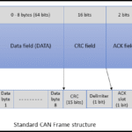
Task 4: Handle communication (e.g., CAN or Ethernet messages).
The RTOS scheduler ensures that tasks are executed according to their priority. High-priority tasks (e.g., airbag deployment) preempt lower-priority ones (e.g., infotainment updates), guaranteeing timely response to critical events.
- RTOS Timer Counter and OS Tick
For task scheduling, an RTOS relies heavily on precise timing. This is achieved using the hardware timer interrupt of the microcontroller (MCU).
Typically, the MCU is configured to generate an interrupt every 1 millisecond (1 ms). Each time the interrupt occurs, the RTOS updates its internal OS counter (sometimes called the system tick).
This OS counter is fundamental because:
It drives task delays (e.g., vTaskDelay(10) waits for 10 ms).
It enables periodic tasks (e.g., running a control loop every 5 ms).
It helps monitor timeouts and watchdog mechanisms.
In automotive systems, having a reliable and precise tick is crucial to synchronize control algorithms, diagnostics, and communication protocols with real-world events.
- FreeRTOS in Automotive Example Projects
One of the most popular RTOS options for embedded developers is FreeRTOS. Although not originally designed for ISO 26262 safety certification, FreeRTOS is widely used in prototyping, proof-of-concept, and even certain production modules (when combined with proper safety wrappers).
Example Project Idea with FreeRTOS:
Imagine building a simple automotive control prototype:
Task A (Sensor Task): Reads the temperature sensor every 100 ms.
Task B (Control Task): Runs a control algorithm every 10 ms.
Task C (Communication Task): Sends vehicle data over CAN every 20 ms.
Task D (Background Task): Logs data to memory whenever the CPU is idle.
By configuring the FreeRTOS scheduler with a 1 ms system tick, these tasks can be easily implemented with deterministic timing. Developers can test algorithms, measure performance, and validate logic before moving to a certified automotive RTOS such as AUTOSAR OS or SafeRTOS.
Conclusion
An RTOS is the backbone of modern automotive software, enabling efficient task management, precise timing, and deterministic behavior. With its reliance on hardware timer interrupts to maintain an accurate OS counter, it ensures that safety-critical functions meet strict timing deadlines. While automotive-grade systems may use certified RTOS solutions, FreeRTOS remains a powerful and accessible platform for developers to experiment, prototype, and learn the fundamentals of real-time embedded software in the automotive domain.
Simple Example for RTOS
include // for usleep() in simulation
// Dummy task implementations
void TaskA(void) {
printf(“Task A executed (10 ms)\n”);
}
void TaskB(void) {
printf(“Task B executed (20 ms)\n”);
}
void TaskC(void) {
printf(“Task C executed (100 ms)\n”);
}
int main(void) {
uint32_t os_counter = 0;
// Infinite loop simulating OS scheduler
while (1) {
os_counter++;
// Every 10 ms
if (os_counter % 10 == 0) {
TaskA();
}
// Every 20 ms
if (os_counter % 20 == 0) {
TaskB();
}
// Every 100 ms
if (os_counter % 100 == 0) {
TaskC();
}
// Simulate 1 ms system tick (like hardware timer interrupt)
usleep(1000); // sleep for 1 ms
}
return 0;
}
How It Works
os_counter simulates the OS counter (system tick).
Each loop iteration = 1 ms tick.
If the counter is divisible by 10 → Task A runs.
If divisible by 20 → Task B runs.
If divisible by 100 → Task C runs.
usleep(1000) is just for simulation on PC (1 ms delay). In a real MCU, this would be a hardware timer interrupt incrementing the counter.


Leave a Reply